Introduction
Overview

The Sinclair C5 has an ULA chip (uncommitted logic array), which acts as the central control unit.
I developed a module which can replace this chip and extends it by some additional features (as like a pedelec mode).
What's so special with this?
- Until now, there was no replacement for lost or damaged ULA units.
- This module allows you to operate the C5 as a pedelec bike and therefore absolute legally within the entire EU.
- There is an option to attach and control a motor fan.
- Drive data as like as speed, motor current or battery voltage will be written out on a serial interface and can be received from other devices (i.e. a PC).
- This project is open source and freeware. Everyone is invited to extend it, to modify it or to distribute. See also chapter License.
The project is made up of the following parts.
- a board with the electronics
- the firmware for the microcontroller
- bootloader software
- a Windows program crc_calc.exe to calculate the firmware checksum
- a Windows program uploader.exe to update the firmware via bootloader
About this document
The most easy way to use the replacement module is to exchange the original chip, add one resistor to the control box and remove another one. And that's all.But furthermore there are much more possibilities. I.e. to connect a motor fan, to modify software settings or even to develop own software.
This possibilities require different skills and knowledge. Thus I'm separating the instructions into following chapters:
- for C5 owners (installation of the replacement module),
- for hobbyist (connecting pedelec sensors, modifying software settings, attaching a motor fan),
- for freaks (assembling the module, receiving drive data, develop own firmware).
History
When the Sinclair C5 was developed in the early 1980s, they set value on simple and common components to reduce production costs.
This simplicity and the abstinence of special parts also leads to the fact, that the C5 is so easy to maintain.
But there is one thing which cannot be repaired: that ULA chip.
This chip (an uncommitted logic array) is the "brain" of the C5, so to speak.
If this chip gets lost or damaged, you may still drive the C5 - but without motor supervision and without those nice characteristic LED displays.
As I mentioned in the C5 blog, I was working on a prototype of a tacho unit with big display, keypad, radio controlled clock, and so forth, to replace the entire POD of the C5.
But meanwhile I decided to develop this replacement module instead which replaces only the original ULA chip.
Motivation
The reason to develop the replacement module was to turn the C5 into a pedelec with less effort.
As another motive, I wanted to have an interface to output drive data and - perhaps some day - to receive and display these data with an additional display module.
And last but not least I intended to provide all owners of a C5 a fully working replacement for lost or damaged ULA units.
Features
Following the features, this module provides:
- Measuring battery voltage and motor current
- Driving the LED bar displays for voltage and current as like as the original chip does
- Measuring the motor temperature
- Provides an option to connect a motor fan
- Measuring the speed
- Measuring the pedal rate
- Measuring trip distance
- Pedelec mode - allows you to drive the C5 within the EU without further insurance or accreditation
- Internal self-tests
- Outputs all drive data and system information via a common serial interface
- A bootloader allows to upload new or own firmware
It is a fully-fledged replacement for the original ULA chip and also offers some nice extra features.
License
This project is intended to be copied and - as the case may be - to be improved or modified. Hence, the licenses for the project parts allow explicitly distribution for non-commercial purposes.:
| Part of the project | License | Conditions |
|---|---|---|
| Circuits and board layout |
 Creative Commons by-nc-sa 3.0
|
|
| Firmware |
Creative Commons by-nc-sa 3.0
|
|
| Bootloader software |
Creative Commons by-nc-sa 3.0
|
|
| Uploader tool (source and executable) |
Creative Commons by-nc-sa 3.0
|
|
| crc_calc tool (source and executable) |
 Creative Commons by-sa 3.0
|
|
| All documentation concerning this project |
Creative Commons by-sa 3.0
|
|
Creative Commons, 171 Second Street, Suite 300, San Francisco, California 94105, USA
Glossary
| Term / abbreviation | Description |
|---|---|
| ATmega88 | Used microcontroller for the replacement module. |
| bootloader | Part of the replacement software to upload new firmware or set configuration values. |
| control box | Electronic box below the seat; containing motor relay, high current circuits, ... |
| ESD | Electrostatic discharge. |
| firmware | Part of the replacement software; main program which emulates the function of the present ULA chip. |
| IC | Integrated circuit |
| ISR | Interrupt Service Routine; Function which will be triggered when distinct events occur. |
| pedelec | Kind of an electric bicycle. Motor can be activated only while the driver is pedalling. |
| PN | Programmer's Notepad. Editor for source code. |
| POD | Display and control unit of the C5. Contains the ULA chip. |
| RS232 | A standard for serial data transmission. |
| ULA | Uncommitted Logic Array. Integrated circuit containing the control logic. |
| WinAVR | Software packet with development tools for Atmel microcontroller. |
Technical realisation
Foregoing considerations
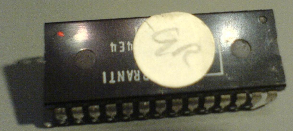
The original ULA chip
A big THANK YOU to all involved authors!
The ULA chip is a 28pin chip with DIL package. This reduces available space for a replacement module to a minimum. The chip is plugged in an IC socket inside the POD. There is plenty space above for connectors or other high components. Directly at the right side of the IC socket there are low profile POD components (some resistors). This allows to extend the board and make it overhanging these components.

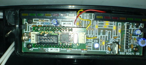
ULA replacement module in the old IC socket.
Since the replacement module uses the present socket, we are bound to the pinout:
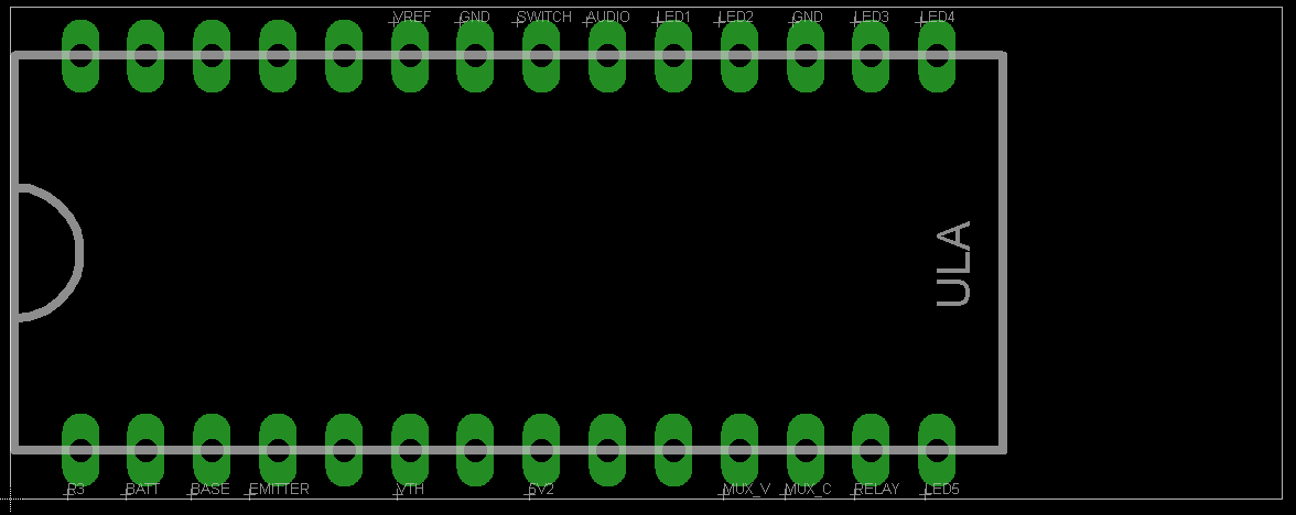
Pinout
The board size is about 49 x 19 mm. Since this is quite cramped I had to use SMD components as far as possible.
Controller
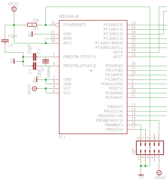
Controller section of the circuit
This controller comes with 8KB flash, 512 Byte EEPROM and can be programmed via a ISP interface (In-System Programming).
The required parts are limited to a minimum:
R1 is the pull-up resistor for the reset signal. C3 is used to dejam the operating voltage and C1, C2 und Q1 provide a clock source.
The ISP interface is connected with the 10pin jack and follows the Atmel standard.
LED display
There are no additional parts required on the replacement board to control the POD LEDs.The signals MUX_CURRENT and MUX_FUEL are directly routed to the multiplex transistors. By the way: during development I noticed that these transistors are exchangeable with BC557 transistors.
The software handles the multiplexing with a distinct timer. Every millisecond it switches between voltage display and current display to provide an illustration free of flickering.
Voltage metering
As you can see here, the battery voltage is routed via a 47k resistor to the ULA chip pin 1.Together with another 15k resistor to ground we get a voltage divider with factor 0.32. This means, 12V battery voltage result in 3.83V on the AD input pin at ADC0 of the ATmega controller. The analog-to-digital converter has a resolution of 10Bit.
This leads to:
12V battery voltage * 15k/47k = 3.83V
3.83V/5.04V * 1024 = 784 (The output voltage of the 7805 regulator is quite exactly 5.04V)
⇒ 784 is the value we expect from the AD comparator for 12V battery voltage.
The selected 15 resistor allows us to measure voltages up to 15.8V:
5.04V * 47k/15k = 15.792V
Since a car battery takes damage if its voltage exceeds 14.4V, the 15k resistor value seems adequaete dimensioned.
Current metering
Measuring the motor current with the original ULA chip goes like this:The voltage drop on a 1mΩ shunt is applied to an operational amplifier in the control box.
1A of motor current results in a voltage drop of 1mV.
This input voltage will be amplified with the op-amp and a variable DAC output from the ULA chip. Concretely spoken this means, the amplifier factor will be increased until a distinct level is reached. With the DAC output given, you can calculate the amplifier factor and with this the motor current value. The big advantage is, that this allows you to amplify even a minimum current to measure it exactly.
I think this is really a very smart method!

47k resistor soldered on the bottom side of the control box board.
However, to measure the motor current somehow anyway I set the op-amp amplifier factor with an additional 47k resistor to a fixed value:
This 47k resistor is located directly at the op-amp inside the control box between pin 7 and pin 3.
Now the amplifier factor is fixed to 1 + 47k/2.7k (⇒ factor 18.4):

green = op-amp output, red = input voltage (1mV equals 1A motor current)
This amplification is suitable to measure currents up to 160A. But you should keep in mind, that due to the long cable between POD and control box, the measurement may be subject of electric interferences which particularly may become noticeable with low currents.
It is very unfortunately that the principle of variable op-amp amplification couldn't be imitated with the ATmega88, but on the other hand now we have this signal line "C5 emitter" from POD to control box left for other purposes: we can use this wire to control a motor cooling fan.
Temperature measuring
Measuring the motor temperature occurs with a temperature dependent resistor. Together with the POD resistors R9 and R20 we get a voltage divider. The voltage on the ULA pin VtH is routed to an AD comparator input and converted by software into temperature in °C.Due to resistor tolerances and nonlinearity the whole thing is not super-exact - but still absolutely sufficient for our purposes.
Motor switch
The button at the steering bar of the C5 to activate the motor is wired with one connector to +12V battery voltage.If the button is pressed, this voltage is routed via a 15k resistor to pin 21 of the ULA chip.
On the replacement board there is another resistor with 4.7kΩ, forming a voltage divider of factor 4.7k/15k = 0.31.
This converts the 12V down to 3.76V which will be applied to an AD comparator input.
Motor relay
The line to enable the motor relay is directly connected with a microcontroller output pin and requires no additional hardware components.Motor ventilator
Since the emitter signal (pin 4 of the ULA chip) won't be needed anymore and since there was a remaining free pin of the ATmega88 left, this line can be used now to activate a fan or another device.But to control a 12V fan or a relay you will need a transistor.
The bootloader allows to configure a temperature threshold at which the ventilator shall be activated.
The ventilator also will be activated if the motor temperature exceeds 70°C.
Speaker
If the motor temperature exceeds 70°C or the current consumption is too high, the piezo speaker in the POD will be activated.Tacho signal
The replacement module provides an option to attach a reed switch, which will be activated by a magnet (attached to one of the wheels).The bootloader allows to configure the wheel circumference.
And so the software can calculate the current driving speed and write it to the serial interface.
Pedal signal
Furthermore, the replacement module provides an option to attach a second reed switch which will be activated by a magnet which is attached to the pedal bevel.So the software can calculate the pedalling frequency.
This information is relevant for the pedelec mode.
Serial interface
The serial interface is used to configure software settings (i.e. the wheel circumference) and to upload new or own firmware via the bootloader.The interface is operated at 9600 baud. It is important to note that the signals are based on 5V level and must not be directly connected with a computer COM port!
To connect with a PC you need a level converter.
General Instruction
Functionality
The replacement module imitates the functionality of the original ULA chip as far as possible. But there are also some differences I like to describe here.Power-on
Directly after power-on the middle yellow LEDs of the POD will flash for 2 seconds. During this time the bootloader program is active and waits for commands to upload new firmware or to change settings:
LED display during power-on phase
How to use the bootloader is explained below.
Main program
After bootloader timeout the actual firmware will be started.It initiates all software and hardware modules, loads configuration settings from EEPROM memory and prompts a welcome message on the serial interface.
Example:
ULA replacement V1164
CRC: 0x5B80E61F

PM:  1
WS:  1280mm
LMX: 250
LMN: 30
FT:  45
This message shows the firmware version number and its CRC32 sum.
The following information show
- whether the pedelec mode is set (PM = 1) or not (PM = 0),
- which circumference (in millimetres) the wheel with the tacho sensor has (WS),
- the maximum speed with motor support available (LMX) if the pedelec mode is set (250 equals 25.0 km/h),
- the minimum speed with motor support available (LMN) if the pedelec mode is set (30 equals 3.0 km/h)
- and the temperature threshold to activate the motor cooling fan if attached (FT in °C).
Main loop
After initialisation and sending the welcome message the following data will be send periodically every 256ms via serial interface:#DIST|SPEED|RPM|TIMEOUT|switch|TEMP|VOLT|VREF|CURR|ENA|COND|TIME
The output starts with a '#' character and is terminated with a newline character ('\n').
| Information | Description |
|---|---|
| DIST | trip distance in mm |
| SPEED | current driving speed in 10th of km/h (123 equals 12.3km/h) |
| RPM | current pedal frequency in RPM |
| TIMEOUT | pedelec mode: time left until motor will be disabled due to non-pedalling driver |
| switch | 0 if the motor switch is not pressed; otherwise any value <=1023 |
| TEMP | AD comparator value of the motor temperature |
| VOLT | AD comparator value of the battery voltage |
| VREF | AD comparator value of the reference voltage (adjustable with the potentiometer inside the POD) |
| CURR | AD comparator value of the motor current |
| ENA | 0 if the motor relay is disabled; otherwise 1 |
| COND | Safety condition. 0 if everything is fine. |
| TIME | System time in milliseconds |
LED display
As like the original ULA chip the LED bars will be operated by multiplexing (but with 1kHz much faster than hitherto). The left bar shows motor current and the right one shows battery voltage.The displayed battery voltage shows the averaged voltage of the last 20 seconds. This means, a short voltage from activating the motor may possibly not be shown while a slow voltage decay will.
With the original ULA chip the voltage bar could only decrease. If the battery voltage revived during a break this wouldn't be shown with the LED bar.
The current display always shows the momentary current consumption.
Safety
If the average battery voltage falls below a reference voltage (adjustable with the potentiometer inside the POD) a voltage error will be indicated. In this condition the motor cannot be activated.If the actual current consumption exceeds a distinct value a current warning will be indicated. If the current consumption of the last 10 seconds exceeds a distinct threshold a current error will be indicated. Both cases deny activation of the motor.
If the motor temperature exceeds 70°C a temperature warning will be indicated. If the temperature reaches 80°C a temperature error will be indicated and the motor cannot be activated.
Failure indication
I consider it very important to determine the reason of failures. At the same time it is also necessary to see the battery voltage level at all times. Hence, for indicating failures we can actually use only the current display.Based on this considerations I implemented the following indications for warning or error conditions (Sorry, I really don't like this GIF flashing all over but in this case it actually makes sense):
| Event | LED display | Speaker |
|---|---|---|
| Voltage warning |
|
off |
| Voltage error |
|
off |
| Current warning |
|
buzz |
| Current error |
|
buzz |
| Temperature warning |
|
buzz |
| Temperature error |
|
buzz |
A white LED above means that the LED bar is working in normal mode. For example: in case of a voltage warning the right LED of the current bar will flash while the voltage bar still shows the actual battery voltage.
Also combinations of these indications are possible. An example:
Well, what does this mean?
Solution:
The voltage bar isn't flashing. So then it's showing the battery voltage as usual. The current bar indicated a current warning (green LED) and a temperature error (yellow-red).
Instructions for C5 owners
This chapter is dedicated to owners of a C5 who received the replacement module completely assembled and who now like to install it.PLEASE READ:
A few words about ESD
Before we start I like to mention that electronic components as like a microcontroller are very sensible against electrostatic discharges (ESD).Electrostatic discharges occur in everyday life nearly everywhere: walking over carpet, handling with plastic foil, wearing fleece clothes, ...
This can cause voltages up to some thousand volts. And although the effective power usually is absolutely harmless for us it still can destroy electronic components.
Hence it is major to discharge yourself before touching the replacement module or anything else connected with it.
You can discharge by special ESD discharge cables but also by just touching a radiator or a water-tap.
Installation
- First you should remove the POD from the C5 and open it.
- Now unplug the ULA chip from its socket.
There a special tools for this but with some skills a screw driver to lever it out works too.
But you should be careful not to break the tiny pins.
- Then the replacement module will be plugged into the socket as shown below:
Replacement module inserted to POD.
Make sure to insert it exactly. Each pin must be plugged.
- The pod many now be closed again.
- Unfortunately we are not finished now: also the control box must be opened.
- Inside the control box there is a 8pin op-amp IC (LM358).
We need to solder an additional 47kΩ resistor between pin 7 and pin 3. You can do that either at the
upper side directly on the op-amp or as shown below at the bottom side:
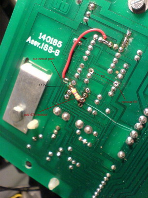
Additional 47k resistor.
Note:
This op-amp tends to get damaged very often. I suggest to power it with +5V on pin 8 instead of +12V. Furthermore a 8pin socket for this IC would be a good idea since it allows you to easily exchange the op-amp in case of a failure.
- Now remove the resistor R5 from the control box. It is located near the op-amp IC.
- The cable harness between POD to control box ends in the control box at connector
X9.
At this connector the wire at pin 8 (C5 Emitter) must be removed.
This wire is directly routed to a microcontroller output pin an can now be used to control a fan.

That's it. After closing the control box you are read to rock and roll!
Instructions for hobbyist
The C5 as a pedelec
To operate the C5 as a pedelec you need two reed switches and two magnets.You can get some form old bicycle cyclometers.
The magnets are attached to one wheel and the pedal bevel and the reed switches so that they will be activated on every turn.
The following illustration shows how to connect the switches to the replacement module:

Connecting the reed switches: P = reed switch at pedal bevel, M = reed switch at wheel
Editing software settings
By default the software is configured to a wheel circumference of 1280mm. This equals the circumference of the Schwalbe BigApple tires.If you have another wheel size you must edit this value.
This is how it's done:
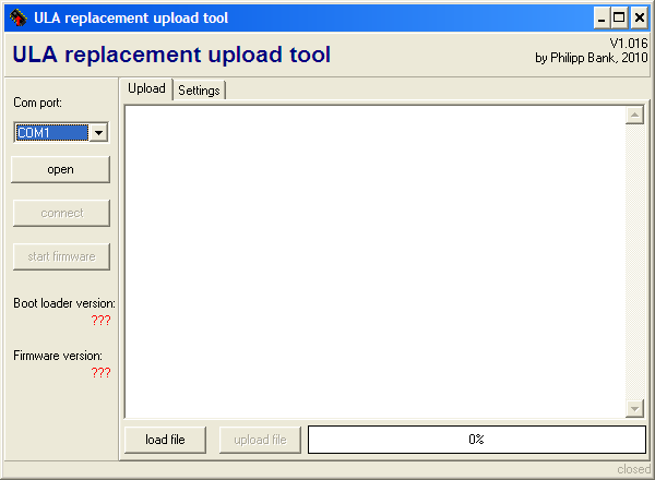
Uploader.exe: ULA replacement upload tool
- On the right side on top of the ULA replacement board (beside the crystal oscillator) there is a 4pin connector.
The pinout is from top to bottom:
+5V

GND

RXD

TXD
RXD is the receiving line of the ATmega, TXD is the sending line. These signal are based on 5V level and must not be directly connected with a computer since this could destroy the microcontroller. You need a level converter to connect with a computer.
There is one available from Pollin-Elektronik which I used and which can be powered with the +5V line.
- Eventually you will also need a 9pin extension cord if the computer port is located too far away.
- Nowadays notebooks and desktop computer rarely have a serial RS232 interface. In this case
an USB<->RS232 adapter will help.
- If you established a link between computer and level converter or respectively the replacement module, you can start
Uploader.exe.
- In ULA replacement upload tool select the correct COM port.
- Now press the button open to open this port.
If this was successful the button connect will be enabled and should be pressed.
Now the program tries to contact the bootloader. - So the next step is to power-on the C5. If everything is working the program should
display a valid bootloader version and the button caption connect will change to reconnect.
The link condition will also be shown at the lower right corner of the program window. - The tab Settings offers some configuration options:
- Pedelec mode: If you set this value to 1 the pedelec mode will be active.
This means that the motor can only be activated at a driving speed between Speed limit min and Speed limit max
and only while the driver is pedalling.
- Wheel size: This value represents the circumference of the wheel with the tacho reed switch.
Driving speed can only be measured correctly if this value is correct. Also the pedelec mode is
dependent on this value.
- Speed limit min and Speed limit max: see pedelec mode.
- Fan activation temperature: This is the temperature when the fan shall be activated (if you connected one).
- Pedelec mode: If you set this value to 1 the pedelec mode will be active.
This means that the motor can only be activated at a driving speed between Speed limit min and Speed limit max
and only while the driver is pedalling.
- The buttons read and write below this table allow to read and write the settings from or to the microcontroller.
- New settings will become valid after a restart of the replacement module.
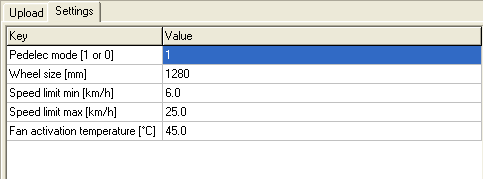
Uploader.exe: settings
Uploading new software
I didn't develop the ULA replacement module just for myself but also for other interested people. But maybe my firmware still has a bug or maybe I will add some features in future. But the fewest of my "customers" may have an own programming device to upload new software into the controller.Hence the ULA replacement upload tool did not only get quite a long name but also the option to upload a binary file containing application firmware into the microcontroller.
This is how it's done:
- Follow the points 1-7 from above.
- In the tab Upload click the button load file and select a hexfile with the
application firmware.
- Press the button upload and wait for the upload operation to complete.
- That is all - restart the C5 and enjoy the new software!
Connecting a motor cooling fan
As described in chapter Installation, the wire "C5 Emitter" from POD to control box won't be needed anymore and can be used to control a fan now.This wire is directly routed to an output pin of the ATmega so please respect ESD rules. This pin can deliver only a few mA which is not enough to directly operate a fan or relay. But with an additional transistor it can be done. This is how it's done:

Connecting a relay to operate a motor cooling fan
The temperature at which the motor fan will be activated can be configured as described in chapter Editing software settings.
Instructions for freaks
It is certainly already very freaky just to own and drive a Sinclair C5. But this chapter is dedicated to those who want to assemble the ULA replacement module or to develop own software.I assume you have skills with handling SMD components, you have very good programming skills with C and some expertise in embedded microcontroller systems.
If this may not be the case I strongly suggest not to build or modify the replacement module.
Not least because I don't want to explain every detail...
To make it short: if you are fluent in C, if you know which end of the soldering iron gets hot and if interrupts, timer CRC32 or IO registers are no foreign words to you ⇒ go on.
If not ⇒ search someone who does to help you (not me).
Assembling the module
The project is stored in the Eagle format. If you don't know yet: Eagle is available as a Freeware Light Edition here for download.
The board size is 49 x 19mm and is a double-sided. The circuit lines are quite thin but still can be etched with hobbyist equipment. It is important to adjust both layers exactly congruent which may require some experience.
I tried to optimise the circuit routing but due to the limited space available there are still many through-connections.
If you like to avoid all the mess with etching you should consider to let someone else making the board. This may not be cheap but I think it's worth its price. I ordered my boards from Q-print.
When starting assembling the components you should start with the ATmega88. Once again I like to remind of ESD protection!
The next things to follow are the resistors and capacitors.
The resistor R_RST won't be placed. Here you have an option to connect a reset button which may be useful for software developers.
Also resistor R6 won't be placed.
Finally place the 16MHz crystal oscillator and the connectors. To adjust the 14pin strips you may use a breadboard:
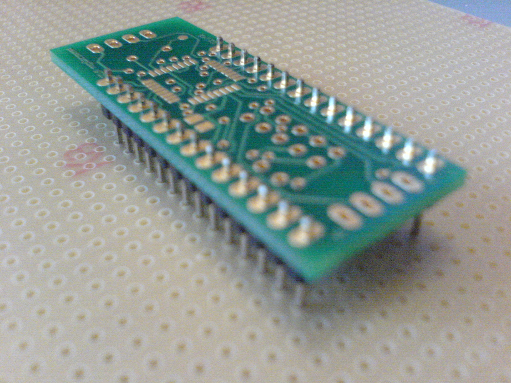
A breadboard can help to adjust the pin strips.
When done with assembling you need to flash the bootloader program via the ISP interface. I'm using a simple STK200 clone for the parallel port as programming device. But any other ISP programming device for ATmega would also do it.
Not later than now it is time to set the fuse bits.
Receiving drive data
After power-on the firmware will prompt the textULA replacement,
followed by the firmware version number and its CRC32 sum on the serial port.
Then a list of configuration parameters (pedelec mode, wheel circumference, ...) follows. See also chapter Main program.
During normal operation every 256ms the firmware will send drive data as described above.
The serial port is available at the connector right beside the crystal oscillator.
The pinout is described in chapter Editing software settings.
To develop a kind of a cyclometer you could use this interface to connect with an additional display unit.
Software
This chapter will give you an overview about the ULA replacement software to allow you to develop own firmware, to extend it or reuse some software parts for completely other projects.General
The software is written in C, was developed with WinAVR and is separated in a firmware and a bootloader project.WinAVR is a collection of open source tools for software development for AVR controller.
I recommend to use the Programmers's Notepad as development environment which is part of WinAVR.
The EEPROM memory of the ATmega contains the configuration values. These are made of:
- E_BOOL bIsPedelec - Pedelec mode active or not
- UINT16 u16WheelSize - Wheel circumference in mm
- UINT16 u16SpeedLimitMax - Maximum speed with motor support available (pedelec mode)
- UINT16 u16SpeedLimitMin - Minimum required speed to activate the motor (pedelec mode)
- UINT16 u16TempFan - Temperature at which the motor cooling fan shall be activated
The flash memory of the ATmega88 is separated in blocks of 64 bytes (pages).
The pages 0..111 (7kB) are available for the firmware, the pages 112..128 (1kB) are occupied with the bootloader program.
At end of page 111, on address 0x1BFA there is a 16bBit version number of the firmware followed by a 32bit CRC sum of the firmware binary at address 0x1BFC.
This checksum is used at runtime to check if the firmware was correctly written to flash memory.
I have written a small command line tool to calculate the CRC sum and insert it automatically in the source code:
CRC_CALC on SourceForge.net
It's a good idea to integrate this tool in Programmer's Notepad:
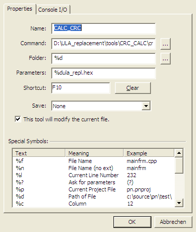
How to integrate the CRC tool in Programmer's Notepad
In PN:
Menu: Tools->Options->Project Tools->Add
And do as shown in the picture.
The order to create firmware is then:
- Make Clean
- Make All
- Execute the CRC tool
- Make Clean
- Make All
It is necessary that the CRC tool (crc_calc.exe) is located in the same directory as ula_repl.hex and global.h!
Fuse bits
Before software is written to the ATmega flash memory you should set the fuse bits. I'm using the program PonyProg for this.Set the fuses as shown in the picture below:
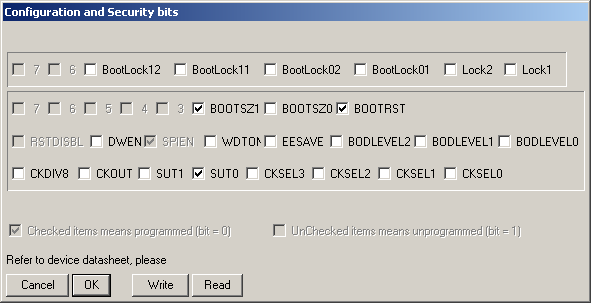
Setting the fuse bits in PonyProg.
Software architecture
The code is designed to make it easy to replace separate modules with less effort or to use them for other projects.Hence all access to ports or registers is abstracted. You find the defines for hardware access in global.h which allows easily adoption to another circuit layout or another processor.
Output via the serial interface is encapsulated in module print and could be redirected to any other kind of interface.
There is a system timer with millisecond resolution in module timer. This timer handles multiplexing the LED displays and controls the speaker.
Furthermore this timer provides flags which will be set at distinct points in time (each 128ms, each 256ms, each 512ms and each 1024ms).
The main loop uses these flags to execute distinct actions (for example send all 256ms drive data via serial port).
Clearing these flags occurs at the end of the main loop.
The module safety forms a central instance for handling errors and warnings. In addition, it continuously performs memory tests to detect flash failures and to verify the firmware download with help of the CRC32 sum.
Software modules
There is an extensive Doxygen documentation of the software at www.cypax.net/projects/ula/docu/index.html. Hence I will limit this chapter to a short description about the firmware modules.| Module | Description |
|---|---|
| adc | Reading analogue voltages |
| current | Calculating the motor current |
| fan | Controlling a motor cooling fan.
See also chapter Motor fan. |
| global | Pin configuration, global definitions and macros |
| init | Central unit to initiate all modules |
| leds | Controlling the LED bars |
| memory | Provides access to EEPROM memory |
| pedal | ISR and methods to calculate pedalling rate |
| Redirects stdout access to the serial interface | |
| relay | Enabling/disabling the motor relay |
| safety | Central safety module.
Performs self-tests and handles warnings and errors. |
| speaker | Low-level control of the speaker |
| speed | ISR and methods to calculate driving speed and trip distance |
| switch | Detects whether the motor switch is pressed or not. |
| temp | Calculated the motor temperature |
| timer | System timer
See also chapter Software architecture. |
| uart | Interface for serial communication |
| ula_repl | Main module of firmware
Contains the main() entry point and handles all functions which are not triggered by interrupts. |
| voltage | Calculates the battery voltage |
| xtypes | Declaration of global types |
The module ula_repl contains the entry point of the firmware.
This module also contains the main loop which performs all interrupt independent actions.
Most of these actions are executed only at regular intervals.
To do so, the timer flags are evaluated (see chapter Software architecture).
In every main loop cycle the function safety_MemoryTest() from the safety module is called to continue the flash memory self-test.
The memory test calculates a CRC32 sum from the flash memory area 0..7164 and compares the calculated value with the comparison value at address 7165..7168.
This serves two purposes:
On the one hand it assures that there are no random memory failures which would cause unexpectable software behaviour, on the other hand it checks whether the last firmware upload was completed successfully.
If the memory test should fail the program calls the function safety_SafeMode(), deactivates all interrupts, disables the motor relay and activates the fan (if there is one attached).
Only a reset leads out of this function.
The basic functionality of the timer module is located in its ISR. Here, the multiplexing of the LED bars occurs: every millisecond the timer changes from voltage display to current display and vice versa.
In addition, the timer module also handles the speaker sounds in case of a temperature or current warning.
Contrary to the original ULA chip the speaker will not scream shrill but buzz pulsed (which I consider much more pleasant).
Hardware
Circuit
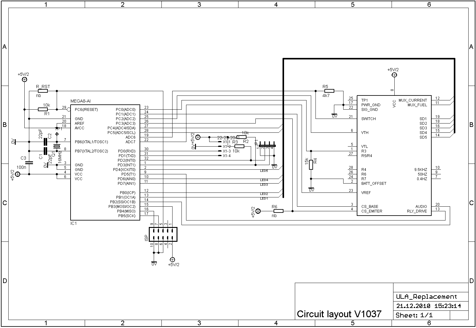
Circuit of the ULA replacement module. Click to enlarge.
Board
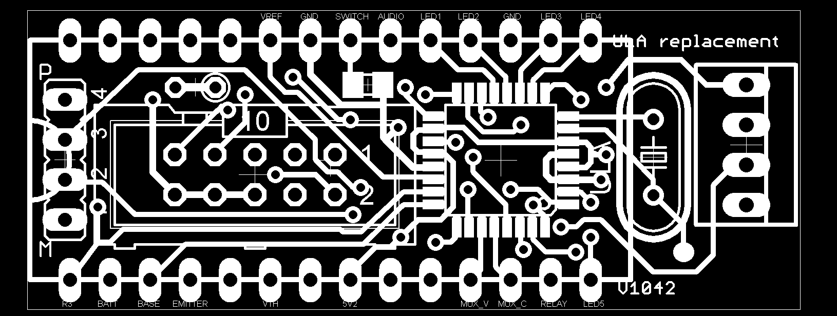
Top side of the board. Click to enlarge
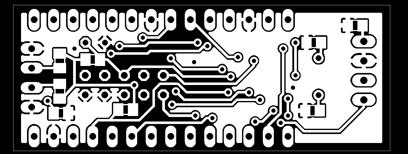
Bottom side of the board. Click to enlarge.
Resources
Files
- Project download (3.1MB) from SourceForge
Separate downloads:
- Eagle circuit and board layout (47KB)
- Software (2.6MB)
- crc_calc.exe (92KB)
- Uploader.exe (624KB)
Related links
- C5 project on cypax.net
- Doxygen documentation of the firmware
- ULA replacement project on SourceForge
- Download section on c5alive.co.uk (via archive.org)
- WinAVR homepage
Updates
So, 23th January 2011
Firmware version 1.172 and bootloader version 1.042.New with this versions: It's now possible to configure the number of magnets for the pedal reed sensor and the speed reed sensor.
If you lose one magnet, pedal rpm or speed value will be incorrect, but the motor is still available.
This is also explained here: http://c5alive.co.uk/forum/index.php?topic=1636.msg12965;topicseen#msg12965.
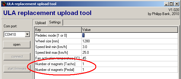
Entering the number of magnets in the Upload-Tool.
Thu, 05th May 2011
Wrong pin labeling in documentation.The documentation said that the additional 47k resistor should be placed between pin 7 and pin 5 which is wrong!
Correct: between pin 7 and pin 3, as like as shown in the pictures above.
So, 23th January 2011
Firmware version 1.172 and bootloader version 1.042.New with this versions: It's now possible to configure the number of magnets for the pedal reed sensor and the speed reed sensor.
If you lose one magnet, pedal rpm or speed value will be incorrect, but the motor is still available.
This is also explained here: http://c5alive.co.uk/forum/index.php?topic=1636.msg12965;topicseen#msg12965.
Entering the number of magnets in the Upload-Tool.
New with this versions: It's now possible to configure the number of magnets for the pedal reed sensor and the speed reed sensor.
If you lose one magnet, pedal rpm or speed value will be incorrect, but the motor is still available.
This is also explained here: http://c5alive.co.uk/forum/index.php?topic=1636.msg12965;topicseen#msg12965.
Entering the number of magnets in the Upload-Tool.
So, 15th May 2022
Wrong pin labeling in English documentation.Can you believe that?! More than eleven years later someone still found a typo in the text.
In chapter Installation it said "We need to solder an additional 47kΩ resistor between pin 5 and pin 3.", which is wrong.
Correct: "We need to solder an additional 47kΩ resistor between pin 7 and pin 3." - as like the picture shows it.
A big THANK YOU to Y for noticing me.