Overview
What is this?A circuit to connect with accumulators, which warns the pilot with blinking signals against deep-discharging the batteries.
Features?
Costs less than 4 Euro, minimal effort, reliable, multifunctional, usable for many types of batteries.
For what types of accumulator?
All types (not only LiPo) with 6V to 15V voltage.
What do I need?
Some basic experiences in soldering, understanding simple circuit diagrams.
Description
Als you may know, lithium accumulators don't like to be supercharged ur discharged too much.A supercharged LiPo might explode and seriously harm persons or damage things around.
You can avoid this by using a adequate automatic charger.
(Please note: you also have always to superwise the charging process even when using automatic chargers!)
When a LiPo ist discharged too much, it is usually quite less dangerous.
Though it still can catch fire, deep-discharge will mainly affect in loss of capacity.
And that's the point: the pilot doesn't have any information about the actual battery voltage. He can only estimate the expected power consumption to get the remaining capacity.
Meantime there are special controllers for lithium accumulators, which limit or disrupt the current flow if voltage reaches critical values.
This is all right for boats or cars. But when using helicopters, this limiters can cause a crash.
As a alternative there are voltage meters, which warn the pilot by blinking and beeping if the voltage is too low.
The following circuit shows you how to build such a warning device by yourself.
It will cost you only a few Euro and warns you against discharging a 3-cell LiPo accumulator by a blinking LED.
The accumulator voltage is used as supply voltage and current consumption is very low.
Circuit
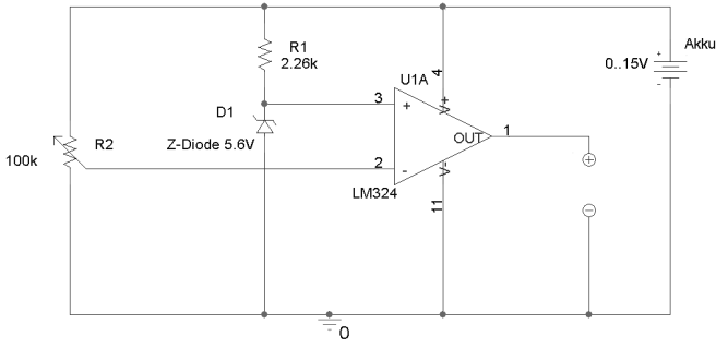
Function
The core of this circuit is a LM324 operational amplifier.This op-amp works with supply voltages from 5V to 15V and doesn't need a dual power supply.
It compares a reference voltage of 5.6V with the accumulator voltage.
A Zener diode provides the reference voltage.
R1 limits the current through this diode.
The op-amp output voltage is:
UOUT = UZENER - x * UAKKU, whereas the factor x can be adjusted with the poti R2 from 0 to 1.
Because of the missing negative supply voltage, UOUT cannot become negative and so, the output voltage will be 0V as long as UAKKU has reached the adjusted voltage. Then UOUT will rise to UAKKU. On the pins (+) and (-) you can access the output voltage. In this case we will use it for a blinking LED, connected in series with a super-bright red LED. But you may use it also for other purposes...
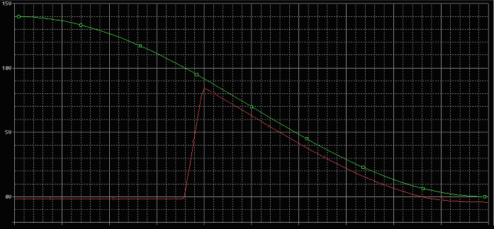
Example for an 11.1V LiPoly accumulator.
The point from which the output voltage increases can be adjusted with the poti.
Alternative for other accumulators
Above dimensioning was for 3-cell lithium accumulators.For use with an 2-cell accumulator, you just need to replace the 5.6V Zener diode with an 3.1V Zener diode.
R1 is then twice as high (e.g. 5.6k).
For other accumulators with other minimum voltages you use Zener diodes with voltages about UAKKUmin * 0,5 and a value for resistor R1, which limits the current in R1 to max. 5mA.
The maximum current through R1 is given by: (UAKKUmax - UZENER) / R1
UAKKUmin stands for minimum battery voltage
UAKKUmax stands for maximum battery voltage
The operating voltage of the op-amp (5V to 15V) doesn't allow to use this circuit with 1-cell or more than 3-cell LiPo accumulators.
Therefore is should only be used with accumulators with voltages from 6V to 15V.
Assembling
What you'll need
You will need following things:(All order numbers from www.conrad.de, prices as at July, 2006)
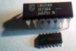
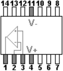
LM324:
Parts
-
1x LM324 SMD 0,31€
Order No. 151840-LN
oder
1x LM324 DIP 0,51€
Order No. 175838-LN
-
1x Zener diode 5.6V 0,26€
Order No. 180580-13
Or, if you need an Akku-Protector for 2-cell LiPolys, you take a 3.1V Zener diode.
-
1x resistor 2.26k 0,13€
Order No. 442313-LN
Or, if you need an Akku-Protector for 2-cell LiPolys, you take a 5.6k resistor.
-
1x Poti 0,60€
Order No. 421082-12 -
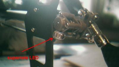
1x LED red super-bright 1,00€
Order No. 183052-12
(you also may find very bright LEDs in optical computer mice...)
-
1x blinking LED red 1,00€
Order No. 173436-12
-
1x tin-solder 0,5mm 10g 1,45€
Order No. 812838-13
-
soldering iron 12V 5,50€
Order No. 830283-13
Furthermore you will need an adjustable power supply, some thin wire, thin cable (red and black), and a voltage meter. And some time.
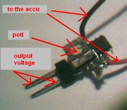
Pin assignment
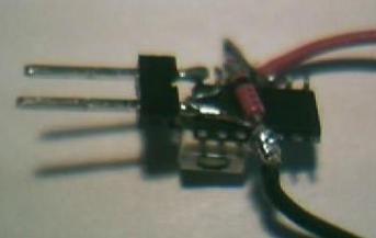
If it is assembled, it may look like this:
Adjustment
Conntect the LEDs with the output pins and bring the poti to central position.Now, connect the circuit with the adjustable power supply (as if it would be an accumulator).
If you have a 3-cell accumulator, adjust it to 9.4V - for 2-cell accumulators to 6.4V.
And now turn the poti until the LEDs start blinking.
Now increase the supply voltage - the LEDs should stop blinking.
If not, turn the poti back and retry again.
After 2 to 3 trials, you should find the right point.
Well, and that's it!
Connect the Akku-Protector with the battery - and done!
A hint: apply the LEDs at the tail of your model, because in the majority of cases this part will face away from you.
Some notes
The output voltage is as high as the battery voltage, when the battery reaches the critical point - this should be considered, if you connect other devices to the output.Furthermore I like to mention that I used my components not from the Conrad shop but from old scrap.
So naturally there will be small differences between my parts and my circuit and yours. It's up to you to make sure, that your components cope with the given voltages and currents.
And now:
have fun with building your Akku-Protector!!!